
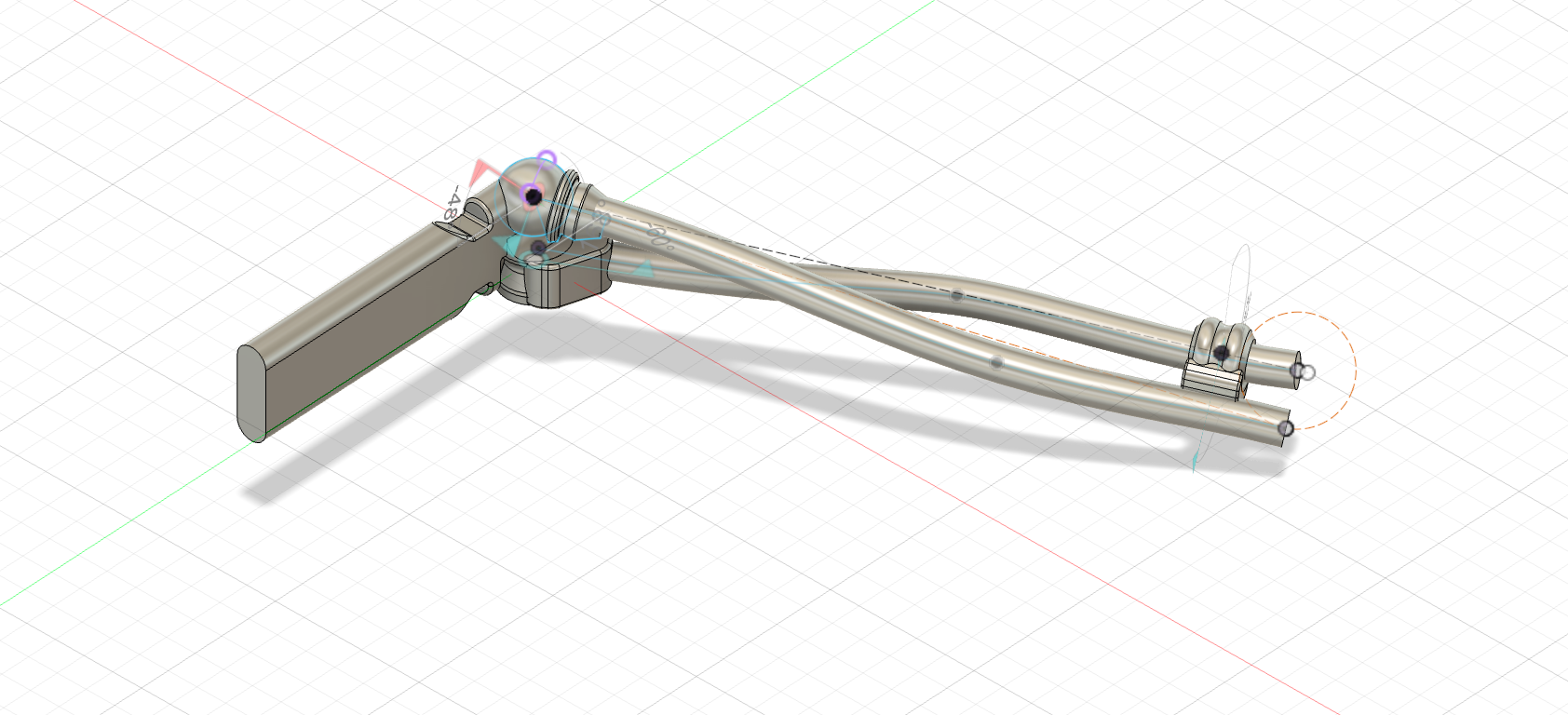
I am designing a mechanical manipulator as a "helping hand" for the workbench. And instead of classical motor operated robot manipulators I have decided to follow the actual human arm anatomy principles. The result will be a stationary mechanical hand-like manipulator operated by artificial muscles that can perform various tasks at the workbench. This is a first from the series of summaries of the process I went through while designing this manipulator.
Intro: Arm Bone Structure
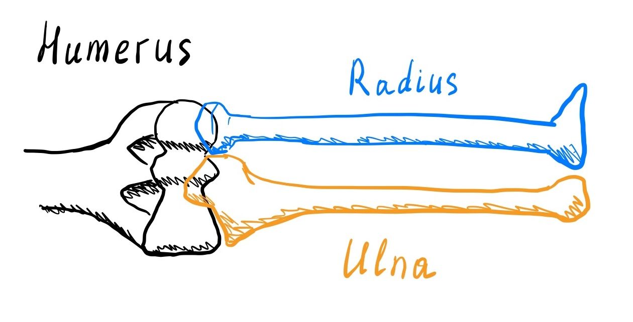
The elbow part of an arm contains 3 bones: humerus, ulna, and radius. But these 3 bones have 4 joints most of which of different kind. Let’s go through each joint one by one.
Joint 1. Humerus and Ulna
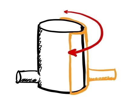
Anatomical terminology defines this type of joint as a hinge joint. This has only one degree of freedom. When ulna is collinear with humerus the forearm is fully extended. Opposite extremum, when is when ulna is parallel to humerus is called fully flexed. Motions towards corresponding positions is called extension and flexion correspondingly.
In its basic form the hinge joint is just a cylinder with a pipe sector sliding around it.
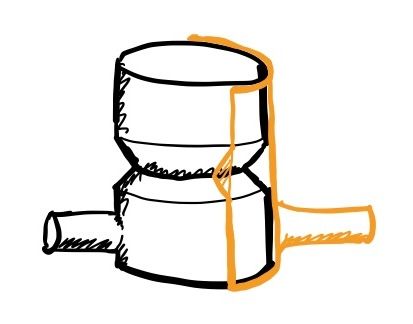
However in such configuration the outer joint would slide along the rotation axis. To eliminate this movement we need to add 2 edges that would prevent sliding in both directions. The easiest is to add a v-groove and make the corresponding feature on the outer part of the joint.
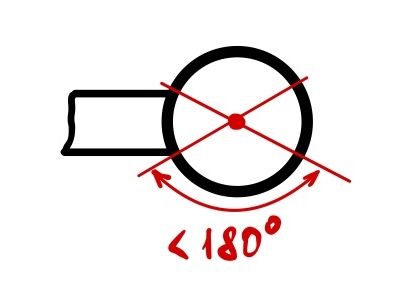
This gives us one part of geometry of a joint between humerus and ulna. Now let’s look at the movement range and how the rest of the bone connects to the joint. Full range of motion of this joint is slightly less than 180˚. The more the outer part wraps the joint the greater is the stability of the joint. But wrapping the outer part fully around the joint, like it is done on a common door hinges, is excessive and would make it harder to assemble. Even wrapping angle over 180˚ would rely on the flexion of the part for assembly, so let’s set the limit of how much the outer part can wrap around the joint to 180˚. On top of that the point of bone connection also influences the wrapping angle (fig. 4).
However this is only a problem in 2-dimentional space, in 3d we have more freedom. The effective wrapping angle is between the furthest points around the axis and if we combine angles less than 180˚ in such way that they extreme points we can get the desired wrapping angle.
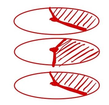
So if we instead design the bone attachment with this in mind we will can get such design
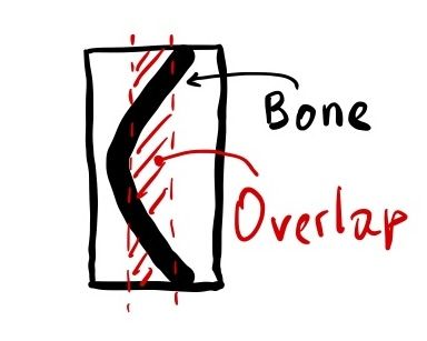
So the final outer hinge would contain a protruding end from one side and a dip on the other end of the shape