
I found myself in an unplanned vacation and decided to get back to my radio engineering hobby. Bought STLINK and a couple of ST's latest chips. And then it happened again. The lack of proper usable tools. I was hoping that the embedded world would have that figured by now. I was wrong.
I got myself the STM Cube IDE thingy. Assembled circuit. Created a basic program. Attached wires. Tried to connect. Fixed wiring. Finally connected.
I have to say that the configurator they have there is a really nice tool, but the code it generates is a pure nightmare.
That day everything worked. Then as my setup went more complex the functionality started falling apart. The first thing that broke - debugging. Ever since that day I was not able to attach the debugger to my MCUs. The next thing that broke - STM Cube Programmer.
So there I was, struggling with ST's IDE from hell. Day by day it was sucking all the happiness out of me. Then I found some information like this guide and it helped me immensely. So I got it sorted out. Which brings me here, to the point where I want to share this knowledge with other poor souls who can find themselves lost in attempt to get going and understand how programming microcontrollers work.
Oh, and I'll be using macOS.
The Overview
The goal here is to create software, convert it to machine code and upload it to the microcontroller. Bonus points for in-circuit debugging.
The Language
I have some experience with C++ therefore I'll be using C. It's also a typical language (assembly?) to write embedded software which means there would be plenty of materials and tools on the internet.
The Compiler
There are not so many options for this setup. You can use gcc. Not just gcc, but use a specific build of it that is able to generate code for the used processor
The Build System
CMake. Many people hate it. It can be hideous. But if you know how to do it properly it is a very nice tool and currently there are no alternatives. On one end we have make, on the other end are tools like Bazel, Buck, and such. Make is way too antique for my taste. And from my recent experience with Bazel I can say that it's too immature. But I hope one day it will show us the way.
The Hardware
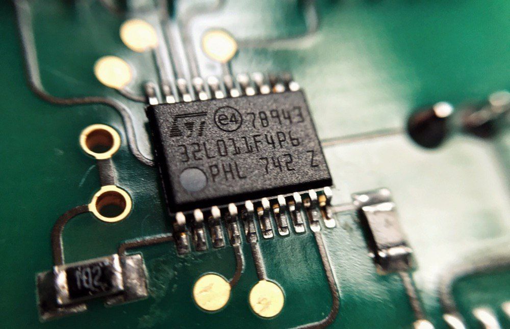
I have bought the microcontroller STM32L011F4 with 32 bit ARM Cortex-M0+ processor. Oh and they are often referred to as microcontrollers or MCUs (microcontroller units). They are not called microprocessors or processors because processor is only a part of it. The other parts being memory (RAM, flash, EEPROM, etc), peripheral devices (timers/counters, communication interfaces, etc.), clock generators.
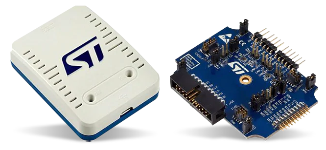
To connect this microcontroller to the computer I bought the latest STLINK-V3SET which is a debugger/programmer.
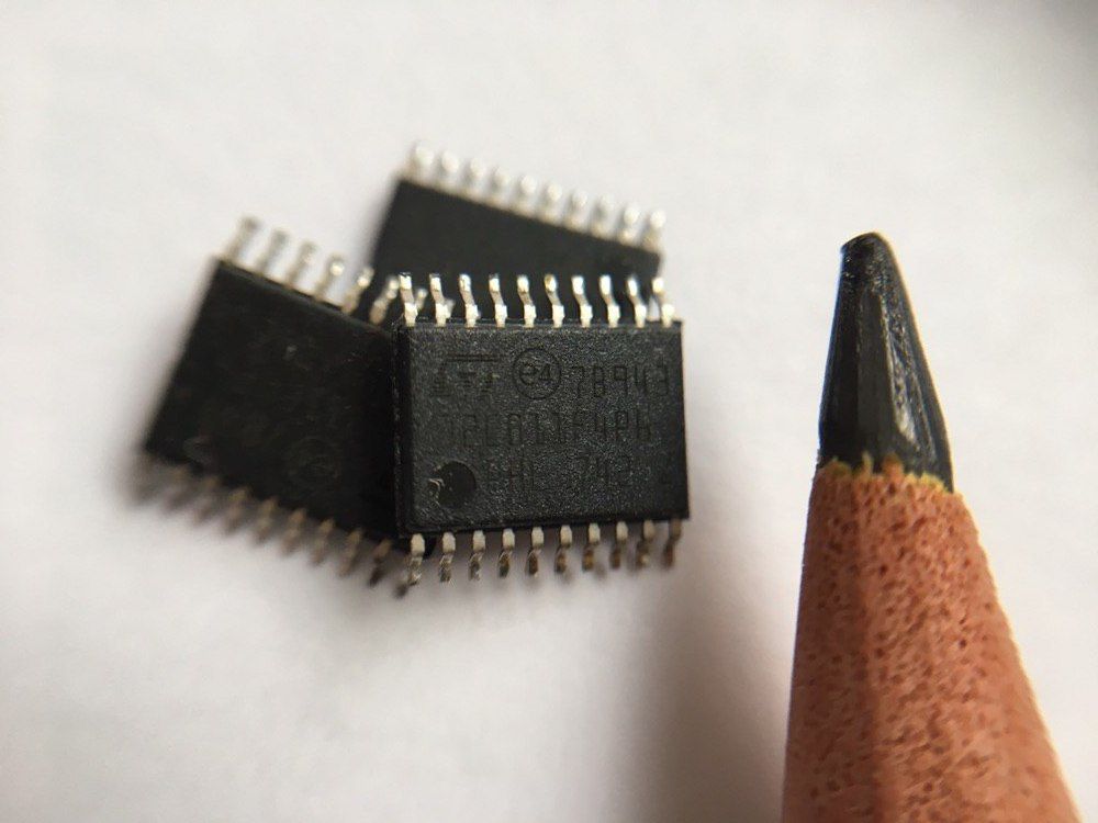
I would not recommend buying standalone microchips because it requires a whole lot of setup and experience in soldering tiny chips the size of a pencil tip.
Luckily there is a huge variety of evaluation boards that have almost everything you might need. Like this NUCLEO-F303RE which already comes with ST-LINK debugger/programmer. The best part is that you can buy a decent board for only 16 euros.
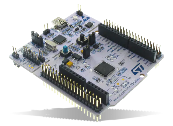
And even if this guide won't help you figure out the bare C programming of microchips you can always switch this board to Arduino Uno mode.
Writing the Program
I'll start with the most simple C program for a microcontroller. I'll get back to the programming part but for now, it's not the most important part. I need to configure the whole pipeline first.
int main(void) {
	while(1);
}The infinite loop is essential here as a microcontroller should never stop while it's on.
Compiling
The compiler needs to match the processor type. My MCU has an ARM processor. Therefore I'll be using arm-none-eabi-gcc (if you're wondering where these words come from google "target triplet"). For some time I was confused where to get the compiler from. It turns out that there is really only one place - the ARM itself. With the help of the community they develop the toolchain for ARM processors which includes the compiler I need.
For macOS I installed it with this formulae:
brew tap ArmMbed/homebrew-formulae
brew install arm-none-eabi-gcc
Because I'm cross-compiling I need to set up the toolchain file. There's not much to it - just general information for CMake on how you build for your platform.
# Cross compiling. "Generic" is used for embedded platforms
set(CMAKE_SYSTEM_NAME "Generic")

# Compilers
set(CMAKE_C_COMPILER "arm-none-eabi-gcc")

# Tells CMake not to try to link executables during its interal checks
set(CMAKE_TRY_COMPILE_TARGET_TYPE STATIC_LIBRARY)And create a CMakeLists.txt file.
# Always start with version requirement - it's a requirement
cmake_minimum_required(VERSION 3.12)

# Tell CMake to use our toolchain file
set(CMAKE_TOOLCHAIN_FILE "${CMAKE_CURRENT_LIST_DIR}/toolchain.cmake")

# And start a project
project("cmake-stm32")

set(CMAKE_C_STANDARD "11") # C11

add_executable("${PROJECT_NAME}" "main.c")
# Produce a file 'program.elf' that can be uploaded to the MCU
set_target_properties("${PROJECT_NAME}" PROPERTIES OUTPUT_NAME "program.elf")


# Compile options and definitions that should be set globally
# For local to the project use `target_compile_definitions`
add_compile_options(
	# CPU specific
	"-mcpu=cortex-m0plus"
	"-mfloat-abi=soft"
	"-mthumb"
	# Non-CPU specific
	"--specs=nano.specs"
	"-ffunction-sections"
	"-fdata-sections"
	"-fstack-usage"
	# Other options
	"-g3"
	"-c"
	"-Os"
	"-Wall"
)

# Set the linker flags
# Unfortunately this is the best way to set the linker flags in CMake
set_target_properties("${PROJECT_NAME}" PROPERTIES LINK_FLAGS
	"-mcpu=cortex-m0plus \
	-mthumb \
	-mfloat-abi=soft \
	-T\"${CMAKE_CURRENT_LIST_DIR}/stm32l011f4.ld\" \
	-Wl,-Map=\"${PROJECT_NAME}.map\" \
	-Wl,--gc-sections \
	-static \
	--specs=nano.specs \
	-Wl,--start-group -lc -lm -Wl,--end-group"
)
The compiler options have three parts ordered by their importance:
- CPU specific options
- Non-CPU specific options
- Other options
CPU Specific Compiler Options
These options need to match your processor.
1. For my CPU I need -mcpu=cortex-m0plus. If you're using the STM32F303RE development board you need this to be -mcpu=cortex-m4 because the processor there is ARM Cortex-M4. By this point, you might be wondering where do I get this whole information from, the answer is documentation. In the form of datasheets mainly. Once you get an MCU the very next thing you need to get is its datasheet. It contains all the required data about your MCU.
2. My CPU has no hardware support for floating-point, therefore, I need to tell the compiler to emulate it in software with -mfloat-abi=soft. The ARM site has it all written for you. Here's a fragment of that table:
| Feature | Cortex-M0 | Cortex-M0+ | Cortex-M1 | Cortex-M23 | Cortex-M3 | Cortex-M4 |
| Instruction Set Architecture | Armv6-M | Armv6-M | Armv6-M | Armv8-M Baseline | Armv7-M | Armv7-M |
| Thumb, Thumb-2 | Thumb, Thumb-2 | Thumb, Thumb-2 | Thumb, Thumb-2 | Thumb, Thumb-2 | Thumb, Thumb-2 | |
| Floating Point Hardware | No | No | No | No | No | Yes (scalar SP) |
| Hardware Divide | No | No | No | Yes | Yes | Yes |
| Single Cycle Multiply | Yes (option) | Yes (option) | No | Yes | Yes | Yes |
| Digital Signal Processing (DSP) extension | No | No | No | No | No | Yes (option) |
So if you have STM32F303RE with Cortex-M4 you want this option to be -mfloat-abi=hard. And also -mfpu=fpv4-sp-d16 because of the DSP unit. More about floating points: Demystifying ARM Floating Point Compiler Options.
3. And finally -mthumb option enables the thumb instruction set supported by all Cortex processors. Thumb a is mixed 32/16 bit instruction set that can fit 2 16-bit instructions in a 32-bit word. This generally would yield a smaller binary size.
You can read more about it on Stack Overflow: GCC -mthumb against -marm.
Non-CPU Specific
The option --specs=nano.specs tells the compiler about the C library. The C library, in this case, is a part of the arm-none-eabi toolchain (that is why it is called toolchain - it has a compiler and all other necessary tools).
Then come helpful options for embedded development in general: -ffunction-sections, -fdata-sections, -fstack-usage. Feel free to experiment with them.
Other Options
-g3- generates debug information.-c- compiles source files but does not link. The output file we need is effectively a static library so we do not need to invoke a linker.-Os- optimise by size. My MCU has very little flash memory and this is the only way to fit everything I need without rewriting it in a more low-level fashion.-Wall- enable warnings. Runtime errors are the last thing you want in the MCU so enable all warnings and fix them.
The CPU Specific Linker Flags
-mcpu=cortex-m0plus- same as for the compiler.-mfloat-abi=soft- same as for the compiler.-T"${CMAKE_CURRENT_LIST_DIR}/stm32l011f4.ld"- linker file. The linker file is the glue between the compiled C code and the microcontroller's memory. I'll explain it further in detail. For now I can say there are 2 ways to obtain it: either by writing it yourself from the datasheet, or from any library package for your MCU (like one from ST's site or opencm3).--specs=nano.specs
The Rest Of Linker Flags
-Wl,-Map="${PROJECT_NAME}.map"- generate a .map file. A very useful file for finding crashes and alternative debugging.-Wl,--gc-sections- remove unused data.-static-Wl,--start-group -lc -lm -Wl,--end-group- linklibandlibm
The Almighty Datasheet
Before I proceed with the linker file and the boot file let me emphasise how important it is to read the datasheet. Get your datasheet (just google "stm32l011f4 datasheet pdf" and the very second link will present you the desired document). Get familiar with it. You don't have to read it whole now - only the general description and the table of contents.
The Linker File
The linker file has instructions for the linker where to put certain parts of the compiled code. There is a handful of predefined sections of program memory, the main ones being:
- Text where all executable code goes
- Data where all initialised global and static variables go
- BSS where all uninitialised globals and static variables go
- Stack where reside runtime dynamic variables
- Heap where dynamically allocated data is kept
The very first thing that linker file normally defines is the representation of the memory model (it is described in the datasheet). My MCU has this memory layout:
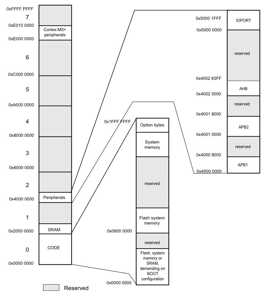
The RAM starts at the address 0x2000 0000 and according to the other paragraph of the datasheet it is 2KB long. RAM can be read, written, and executed, which is translated to the linker file syntax as:
MEMORY
{
	ram (xrw) : ORIGIN = 0x20000000, LENGTH = 2K
}
Next up is the flash memory which should be 16KB and starts at the address 0x0800 0000. This memory can not be written under normal conditions so it has only r and x attributes.
MEMORY
{
	ram (xrw) : ORIGIN = 0x20000000, LENGTH = 2K
	flash (rx) : ORIGIN = 0x08000000, LENGTH = 16K
}
It also has EEPROM but I will skip it for now.
Stack: the processor needs to know where the stack begins. Point it to the very end of the RAM memory. The stack grows downwards so the end of the available RAM is the very first address that can be used. Another caveat here is that the linker script can not set the stack pointer. What it can do instead is to provide the address of the stack so it can be set in run time from code.
PROVIDE(_stack = ORIGIN(ram) + LENGTH(ram));
The code above provides a variable _stack located at the very last address of the RAM.
All is left now is to define the memory sections and assign them to the right segments of the memory (flash or RAM).
SECTIONS
{
	.text : {
		*(.vectors)
		*(.text*)
		. = ALIGN(4);
	} > flash
}
When I first saw the linker script I had so many questions. It took me several sleepless nights to understand it on the level where it is clear for me. Like the part above which is a bit more complicated than the code we saw before.
- Why is there two
.text? - Why are there so many asterisks?
- What's up with that
ALIGN? - What is
.vectors?
I found all the answers. Let me explain.
The command .text : { } > flash declares a memory block called .text and places it in the flash memory. It is not the same as .text section from the program memory I wrote about before; it is a different entity, like a variable name nothing more.
The command *(section) inside a memory block is a way to allocate all of the corresponding program section content.
The second asterisk in *(.text*) is just a wildcard symbol. All segments that start with .text will be allocated there.
The line . = ALIGN(4); asks linker to add padding memory after the previous segment so the next segment starts with the address which is multiple of 4. This is necessary for efficient and correct addressing of the memory in 32 bit CPUs. Because every consecutive section starts right after the the end of previous section in given memory segment.
The *(.vectors) is a segment of memory that I will create in the code. This segment will go to the very beginning of the memory because it serves a very important function - the startup sequence of the MCU.
The Boot File
Which brings us to the boot file. According to the datasheet the boot sequence of the processor is following:
... the CPU fetches the top-of-stack value from address0x0000 0000, then starts code execution from the boot memory at0x0000 0004.
My CPU has several boot modes that define what memory will be mapped to the address of 0x0000 0000. In the normal boot mode this would be the beginning of the flash memory (0x0800 0000). So I have placed a special section called .vectors in this part of the memory.
extern unsigned int _stack; // Provided by the linker file
extern int main(void);

// Let compiler know what section this code belongs to
__attribute__ ((section(".vectors")))
struct {
	unsigned int* initial_stack_pointer;
	void (*reset)(void);
} vector_table = {
	initial_stack_pointer = &_stack,
	reset = main,
};The code above uses the variable _stack that I created in the linker script and a function int main(void) which comes from the code I wrote in the very beginning. Then places the pointers to the top of the stack and the entry point in the right place in the memory.
But there's more. Right after address 0x0000 0000 and 0x0000 0004 comes 0x0000 0008 and this address is also a part of the internal functionality of the MCU. The datasheet should have section Interrupt and exception vectors with the detailed description of what should go there.
Here's a fragment of the table List of Vectors from the datasheet on STM32L011F4
| Acronym | Description | Address |
|---|---|---|
| - | Reserved | 0x0000 0000 |
| Reset | Reset | 0x0000 0004 |
| NMI_Handler | Non maskable interrupt. The RCC Clock Security System (CSS) is linked to the NMI vector. | 0x0000 0008 |
| HardFault_Handler | All class of fault | 0x0000 000C |
| - | Reserved | 0x0000 0010 - 0x0000 002B |
| SVC_Handler | System service call via SWI instruction | 0x0000 002C |
| - | Reserved | 0x0000 0030 - 0x0000 0037 |
| PendSV_Handler | Pendable request for system service | 0x0000 0038 |
| SysTick_Handler | System tick timer | 0x0000 003C |
The complete boot file for my controller looks like this. Creating this file is a purely mechanical process once you get the idea. Simply look at the table and write the corresponding code.
extern int main(void);
extern unsigned int _stack;

void blocking_handler(void) { while (1); }
void null_handler(void) {}

__attribute__ ((section(".vectors")))
struct {
	unsigned int* initial_stack_pointer; // 0x00
	void (*reset)(void);                 // 0x04
	void (*nmi)(void);                   // 0x08
	void (*hard_fault)(void);            // 0x0C
	void (*reserved_0x0010[7])(void);    // 0x10
	void (*sv_call)(void);               // 0x2C
	void (*reserved_0x0030[2])(void);    // 0x30
	void (*pend_sv)(void);               // 0x38
	void (*systick)(void);               // 0x3C
	void (*irq[32])(void);               // 0x40
} vector_table = {
	.initial_stack_pointer = &_stack,
	.reset = main,
	.nmi = null_handler,
	.hard_fault = blocking_handler,
	.sv_call = null_handler,
	.pend_sv = null_handler,
	.systick = null_handler,
	.irq = {
		null_handler, //Window WatchDog
		null_handler, //PVD through EXTI Line detection
		null_handler, //RTC through the EXTI line
		null_handler, //FLASH
		null_handler, //RCC
		null_handler, //EXTI Line 0 and 1
		null_handler, //EXTI Line 2 and 3
		null_handler, //EXTI Line 4 to 15
		null_handler, //Reserved
		null_handler, //DMA1 Channel 1
		null_handler, //DMA1 Channel 2 and Channel 3
		null_handler, //DMA1 Channel 4 and Channel 5
		null_handler, //ADC1, COMP1 and COMP2
		null_handler, //LPTIM1
		null_handler, //Reserved
		null_handler, //TIM2
		null_handler, //Reserved
		null_handler, //Reserved
		null_handler, //Reserved
		null_handler, //Reserved
		null_handler, //TIM21
		null_handler, //Reserved
		null_handler, //Reserved
		null_handler, //I2C1
		null_handler, //Reserved
		null_handler, //SPI1
		null_handler, //Reserved
		null_handler, //Reserved
		null_handler, //USART2
		null_handler, //LPUART1
		null_handler, //Reserved
		null_handler, //Reserved
	}
};Now all is left is to add this file to the CMakeLists.txt, compile, and upload the program.elf to the MCU.
Conclusion
This concludes the setup (oof) for writing code for MCU's without relying on any IDE. This setup is not a complete one, for a full-scale usage of the MCU it needs to be expanded. Also, it is missing other important bits of setup required for other features of the C language. I might cover that in other articles.
Links
- Github repo with the code I have written - https://github.com/Teivaz/cmake-stm32
- The article that inspired me and helped get going - https://geokon-gh.github.io/bluepill/
- The online store where I buy my parts and development boards - https://eu.mouser.com/
- The linker scripts documentation https://access.redhat.com/documentation/en-US/Red_Hat_Enterprise_Linux/4/html/Using_ld_the_GNU_Linker/scripts.html